Sketches
Edges
Faces
Features
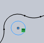
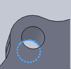
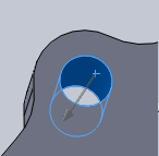
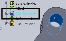
It is very important to understand how to select geometry for the drilling features. Drilling features allow you to select sketches, edges, faces, and features from the SolidWorks FeatureManager design tree or directly from a part in the graphics area.
|
Sketches |
Edges |
Faces |
Features |
|
|
|
|
|
You cannot select a combination of faces and edges. To simplify the process you can only select sketches and edges for a single milling feature, or select faces and CAD features containing faces for a single milling feature.
NOTE: When selecting sketch entities, only the diameter information is imported into the drilling feature. Depth information must be manually entered.
TIP: It is important to understand how the diameter and depth information are recognized by the system depending on your selection. This is particularly important when selecting edges. You must always select the bottom edge of a hole so that the system is able to calculate the depth of the hole.
The Selection Manager for Holes
Selection Options
Select Whole Bodies - Selecting this check box allows you to select an entire body to be processed by the machining operation.
The Selected Items list shows all of the currently selected items for the feature. You can right-click in the selection window to delete or clear selected items.
Parameters
Auto Group - Selecting this check box automatically groups all of the holes of the same diameter and depth into one machining feature. Clearing this check box causes the system to produce a new machining feature for each hole.
Rapid Plane - This is the value that is used as the rapid plane inside of the machining feature.
Tolerance - This value is used in the feature detection based on the type of selections made.
Options
Minimum Hole Diameter - This value is the smallest hole diameter detected that is used inside of a drilling feature.
Maximum Hole Diameter - This value is the largest hole diameter that causes the system to generate a drilling feature.